What Cable Should I Use for My 10G Transceiver Module?
To deploy the optical network, the transceiver module and patch cable are the two basic components. According to the feedbacks of customers from FS.COM, one of the common problems faced by them is what cables they should use for their transceiver modules. To solve this problem, we make this post of patch cable selection guidance. Since the order for 10G transceivers ranks top, we are going to take 10G modules as a reference.
An overview of 10G Transceiver Module
Transceiver module, also called fiber optic transceiver, is a hot-pluggable device that can both transmit and receive data. By combining a transmitter and receiver into a single module, the device converts electrical signals into optical signals to allow these signals to be efficiently transferred on fiber optic cables. As for the 10G transceiver, it refers to the optical modules with 10G data rate. In FS.COM, there are mainly four types of 10G transceivers: XENPAK, X2, XFP, and SFP+. Even though these optical transceivers are all accessible to the 10G networks, they have different matching patch cables and applications.
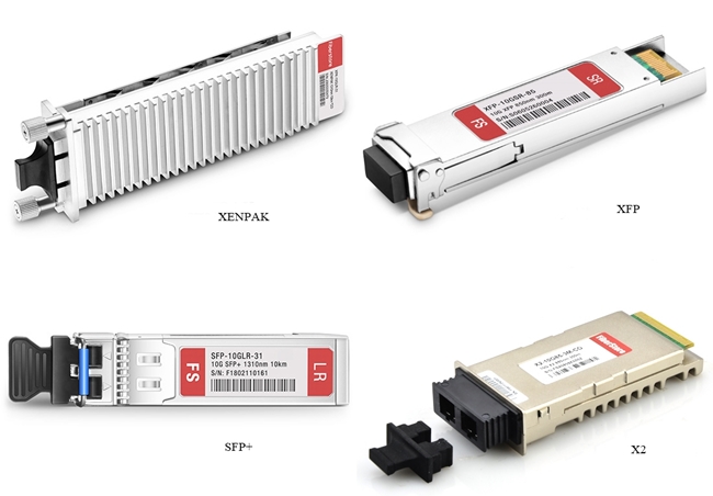
Figure 1: 10G Transceiver Modules
Patch Cable Basics
Apart from
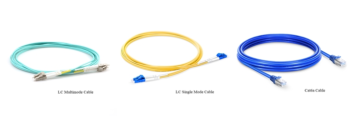
Figure 2: Patch Cables
Factors to Consider When Choosing Patch Cable for 10G Transceiver Module
Recently, most of the 10G transceiver modules are compatible with different brands and support higher data rates. It will be much easier to choose optical modules for your networking than selecting mating patch cables. Based on most applications, there are three major factors that can be taken into consideration: transmission media, transmission distance, and transceiver module interface.
Transmission Media
Classified by transmission media, two types of patch cables can be found in the market: optic fiber cable and copper cable. Correspondingly, there are two kinds of optical transceivers available: copper-based transceivers and fiber optic based transceivers. Copper transceiver modules like 10GBASE-T SFP+, they have an RJ45 interface, connecting with copper cables. Typically, Ethernet cables that support 10G copper-based transceivers are Cat7 and Cat6a cables.
As for the 10G optical modules, they can support higher data rates over optic fiber cables. It will be more complicated to choose fiber cables. Generally, there are multimode fibers and single mode fibers. Based on the specified needs for transmission distance, the answer will be varied.
Transmission Distance
To select cables,
|
Transceiver Type
|
Wavelength
|
Cable Type
|
Transmission Distance
|
|
SR
|
850 nm
|
MMF
|
300 m
|
|
LR
|
1310 nm
|
SMF
|
10 km
|
|
ER
|
1550 nm
|
SMF
|
40 km
|
|
ZR
|
1550 nm
|
SMF
|
80 km
|
As for fiber cables, single mode fiber is used for long-distance transmission and multimode fiber is for short distance. In a 10G network, the transmission distance of single mode fiber (OS2) can reach from 2 km to 100 km. When it comes to multimode fibers, the transmission distances for OM1, OM2, OM3 are 36 m, 86 m and 300 m. OM4 and OM5 can reach up to 550 m.
Transceiver Module Interface
Another factor you need to consider is the transceiver interface. Usually, transceivers use one port for transmitting and the other port for receiving. They tend to employ duplex SC or LC interface. However, for 10G BiDi transceivers, it only has one port for both transmitting and receiving. Simplex patch cord is applied to connect the 10G BiDi transceiver.
Summary
For your 10G network cabling,
How to Troubleshoot Transceiver and Switch Port Through Loopback Test?
Loopback
Loopback is a commonly used term in telecommunications. It refers to the process of transmitting electronic signals or digital data streams and returning to their sending point without any intentional processing or modification. Therefore, by comparing transmitting signals with the receiving signals, the loopback test is used to debug physical connection problems. But what a loopback test means for
Why Need Fiber Loopback Test?
To conduct a fiber loopback test, the communication devices will be involved, like the transceivers and the switch. As you know, the transceiver is the basic component of fiber optic communication network equipment. We can take the transceiver as a case. Conventionally, a transceiver has a transmitting port and a receiving port, in that way, the loopback test can be applied to test the ports to diagnose whether the transceiver is working well and the configuration of the switch is right. For its unique working mode, the test is a convenient way to maintain transceivers. In the next part, we will deliver how to do the fiber loopback test on the transceiver.
How to Conduct Loopback Test?
In this part, we will introduce two types of tests to troubleshoot transceiver and switch port: single-port test and dual-port test.
Tools You Need to Prepare
To perform tests, things you need to prepare are listed below:
- Transceivers (2pcs), such as 10G SFP+ SR transceiver.
- Simplex fiber cable (1 pc).
- Switch (1 pc), like
Cisco switch. - Duplex fiber cable (1 pc).
- Two loopback cables (optional), like LC or SC loopback cable. To know more about loopback cable, you can move to the article: What Is Loopback Cable And How to Use It?
Figure 1: Loopback Cable
Loopback Test Steps
Single-port Loopback Test
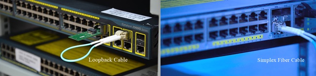
Figure 2: Single-port Loopback Test
1. Connect your transceiver with one simplex fiber cable or loopback
2. Check the software version of the switch.
3. Review the interfaces status to confirm the working status of all ports on the switch.
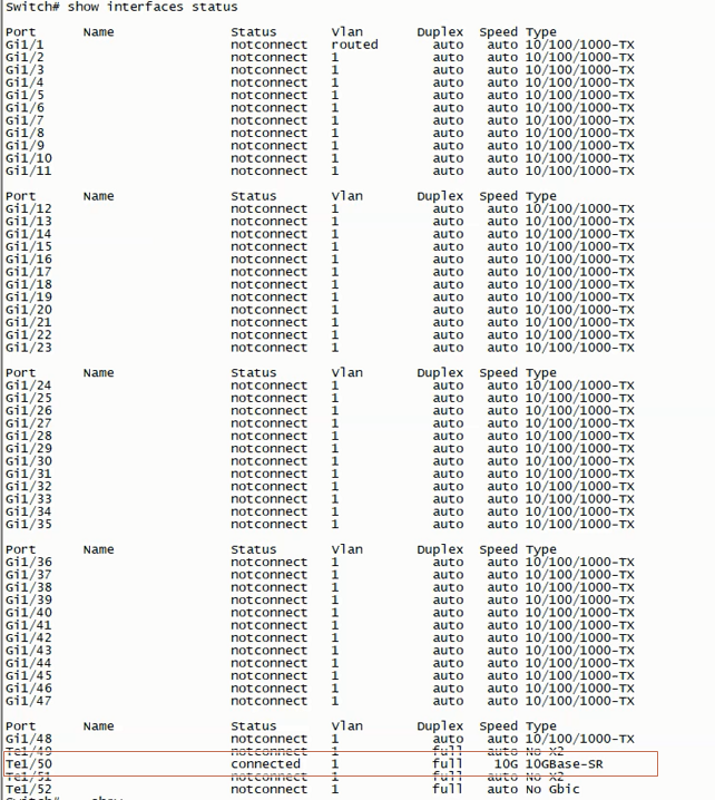
Figure 3: Display the Working Status of All Ports
4. Check the working status of the port you are connecting, such as the port 50 in the following figure.
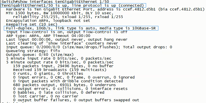
Figure 4: Working Status of Interface 50
5. Go over the DDM information to review whether the transceiver works in normal status.
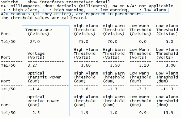
Figure 5: DDM Information of Port 50
Dual-port Loopback Test
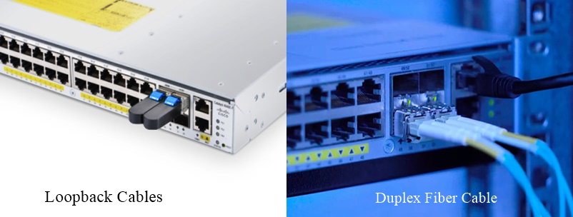
Figure 6: Dual-port Loopback Test
1. Connect two transceivers with one duplex fiber cable or two loopback cables. At this step, you can examine whether the port and transceiver data rate are matching as well as the link is normal or not.
2. Check the interfaces status to confirm the working status of all ports on the switch.
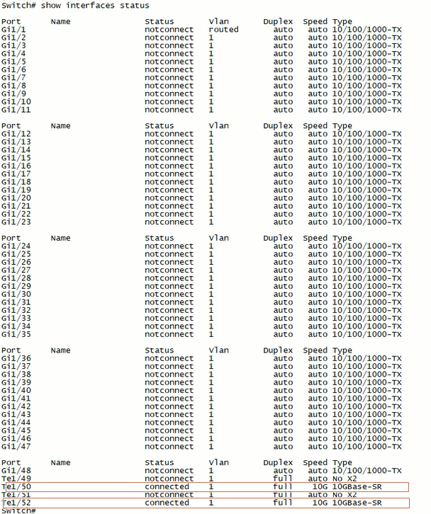
Figure 7: Ports Working Status Display
3. Check the working status of the two ports you are connecting, such as the ports 50 and 52 in the following figure.
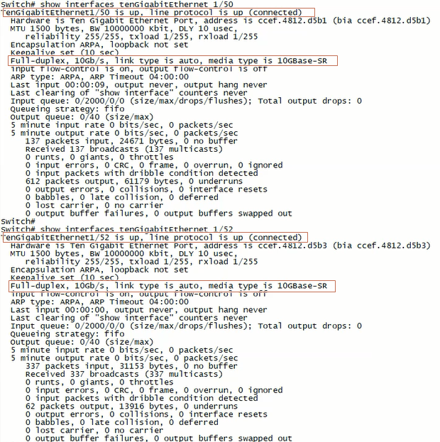
Figure 8: Working Status of Interfaces 50 and 52
4. Go over the DDM information to review whether the transceiver works in normal status.
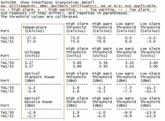
Figure 9: DDM Information of Ports 50 and 52
Summary
To troubleshoot the circuit connectivity as well as the transceiver and the switch port,
FMS 4000E for DWDM Network Solution
In the network era, the demand for greater traffic capacity, higher bandwidth, and better performance over longer transmission distance have never stopped. Under such a context, the optic transport network (OTN) has undergone great changes to survive. At the moment, FS provides their all-in-one dense wavelength division multiplexing (DWDM) OTN solutions. In this post, we will share one of the most popular DWDM solutions: FMS 4000E.
DWDM Network Basics
DWDM
Dense wavelength division multiplexing is a technology based on wavelength-division multiplexing (WDM). It combines or multiplexes data signals from different sources for transmissions over a single fiber optic cable. At the same time, data streams are completely separated. Each signal is carried on a separate light wavelength. In most cases, the dense wavelength division multiplexing technology is applied in metropolitan network.
Optical Transport Network
Defined by the ITU Telecommunication Standardization Sector (ITU-T), OTN is a set of optical network elements (ONE) that are connected by optical fiber links. Sometimes, it’s also called the digital wrapper technology which provides an efficient and globally accepted way to multiplex different services onto optical light paths. This technology provides support for optical networking by using WDM unlike its predecessor SONET/SDH. It’s able to create a transparent, hierarchical network designed for use on both WDM and time division multiplexing (TDM) devices. The OTN is able to support functions, like transport, multiplexing, switching, management, supervision, and builds OTN client (e.g. SONET/SDH, IP, ATM) connections in the Metro and Core networks.
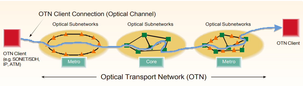
Figure 1: Optical Transport Network
DWDM Network
The DWDM based network refers to a kind of dense wavelength division multiplexing technology based OTN solution. Compared with CWDM, the DWDM uses more sophisticated electronics and photonics, which makes its transmitting channel are narrower than CWDM channels. Therefore, for a DWDM network, it can support more channels and separate wavelengths (up to 80 wavelengths). It can transmit data in IP, ATM, SONET, SDH, and Ethernet. For
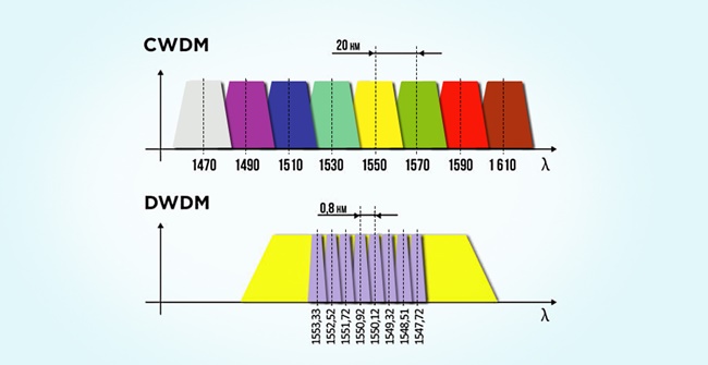
Figure 2: DWDM vs CWDM Wavelength
FMS 4000E for DWDM Solution
In order to make the DWDM OTN deployment easier, FS has launched the high integration FMS WDM transport networks, such as FMS 1800 and FMS 9600E. In this post, we will mainly introduce the most popular solution: FMS 4000E.
What Is FMS 4000E
The FMS 4000E is a device that combines the OTN switching and dense wavelength division multiplexing features and provides unified transmission of all services. It integrates DWDM equipment with OTN function cards (EDFA, DCM, OEO) in a 4U form factor. With FMS 4000E, you can extend the optical link power budget for building long-distance dense wavelength division multiplexing solutions.
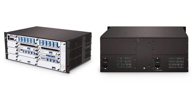
Figure 3: FMS 4000E
Strengths of FMS 4000E
- Supports up to 40 wavelengths via the dual fiber bi-directional transmission mode.
- Transmits up to 105 km with DWDM SFP+ 80km at the rate of 10Gbps.
- Optional function cards to meet various needs (WDM Mux/Demux, EDFA, DCM, OEO).
- Dual AC or DC pluggable power supply and fan unit.
- Supports SDH/SONET, PDH, Ethernet, SAN, LAN, video service transport.
- Scales easily for the ring, end to end and mesh networks.
- Suitable for the enterprise, medical, Storage Area Networks (SANs), data centers, campus optical network
and video surveillance. - Scalable solution for customers to expand capacity as needed. And operating costs and vital resources are greatly saved.
- Ensure the maximum bandwidth for the required capacity and transmission distances.
- Fully managed, configured and monitored remotely via FS.COM intelligent network management unit.
- Simple installation, operation, and maintenance.
- Standards-based and can integrate with third-party solutions.
- The solution can be customized to suit specified customer application requirements.
Solution Topology
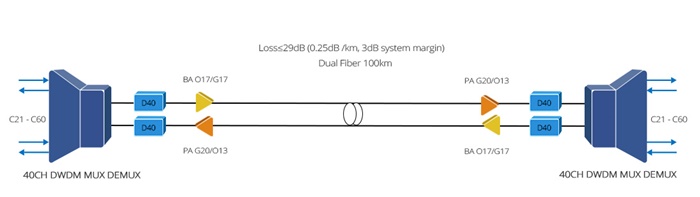
Figure 4: FMS 4000E Solution Topology
Note: This solution does not come with OPM, OPD, OLP, OSW card.
Matching Products
- 40CH C21-C60 DWDM Mux Card ( 2pcs)
- 40CH C21-C60 DWDM Demux Card ( 2pcs)
- 20dB Gain Pre-Amplifier DWDM EDFA Card (2pcs)
- 17dB Output Booster EDFA Card (2pcs)
- 40km Passive Dispersion Compensation Card (4pcs)
- FMT 4U Managed Chassis (2pcs)
- LC/UPC Single Mode Fixed Fiber Optic Attenuator, 3dB (1pc)
Summary
Obsessed with higher bandwidth applications and the simplest operation, the OTN has broken through its traditional operation and make inroads into the highly integrated OTN. Undoubtedly, the DWDM solution will be the one having the last laugh after networking ups and downs. To share that last laugh, FS provides its DWDM solutions for multi-service optical transport over ultra-long distance: FS WDM transport platform (FMS) series. They help our customers to build an access transport network with more flexible service access, easier
42U Network & Server Cabinet Recommendation
Meeting the increasing high-density cabling, the server cabinet or network cabinet is often chosen as the solution, especially for enterprises from the telecommunication industry. Sometimes, it may be confusing to choose a specified type. To solve that, we will recommend a favorable choice for you: 42U network & server cabinet.
An overview of 42U Network & Server Cabinet
For this FS 42U network & server cabinet, just as its names shows it is a multifunctional device. It can be both used as the 42U network cabinet and the 42U server rack cabinet, which will be fully introduced in the next part. In this part, we will look through features and highlights shared by FS 42U network & server cabinet.
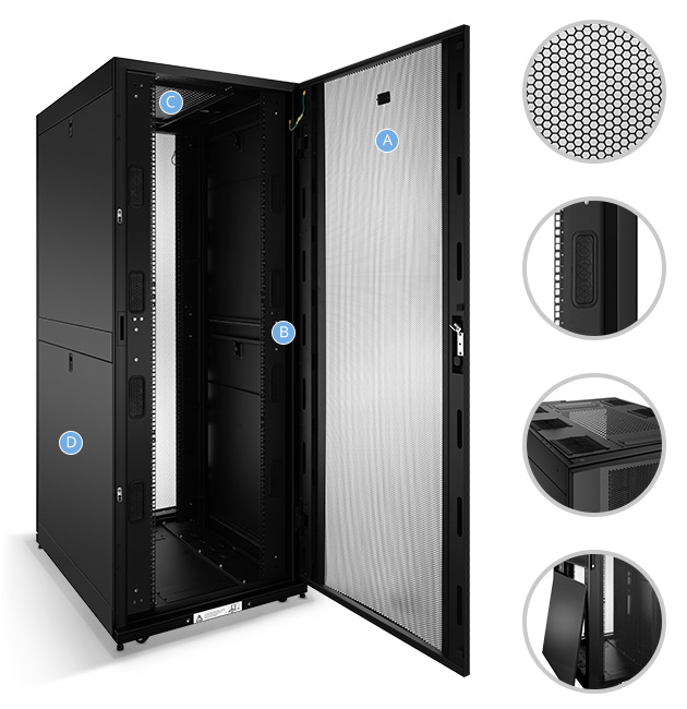
Figure 1: 42U Multi-use Cabinet
Product Features:
- Doors: With the arc hexagonal perforated front and rear doors (section A in Figure 1), massive ventilation for servers and network equipment can be guaranteed. Besides, equipped with removable hinge system, the split rear door will be easily removable in case of the maintenance for devices.
- Panels: The top panel (section C in Figure 1) is made as the brush strip cable entry type for an easy overhead cabling access. Still, the design can maintain proper hot aisle or cold aisle flow. As for the split side panels (section D in Figure 1), they are locking removable with half height. In that way, the size and weight can be both reduced for an easier handling and access to equipment.
- Grounding System: For this 42U multi-use cabinet, it utilizes quick-release ground wires to ensure the entire cabinet is fully bonded.
- Equipment Rails: The equipment rails come with cable access holes (section B in Figure 1) and RU markers. Combined together, the designs can maintain the proper airflow within the cabinet and offer precise adjustment for the rails.
- Accessories: The FS 42U multifunctional cabinet provides 2 pieces of full height PDU brackets, which allows an easier integration between rack PDUs and cable managers. Apart from that, four pieces vertical cable managers on front rails are also offered for easily organizing and locating large cable bundles.
Application Scenario
As we mentioned in the beginning, the FS multifunctional 42U cabinet comes with two flavors. In this part, we will illustrate how it is applied in different scenarios.
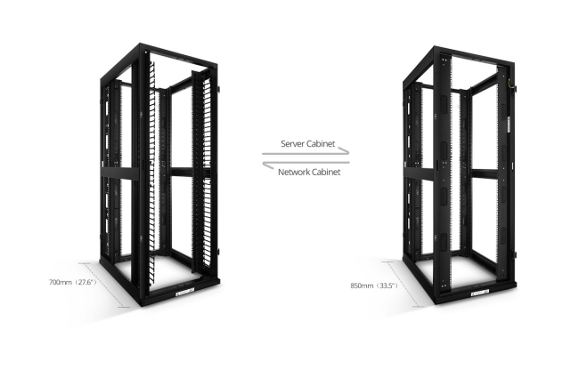
Figure 2: 42U Network & Server Cabinet
Server Rack
When the cabinet works as the 42U server cabinet, the following products are suggested:
- Servers, rack-mount switches, PDU
- Rack-mount cabinets/enclosures (1U/2U), MTP fiber patch panels(FAPs)
- MTP cables or other regular fiber patch cables
- Horizontal cable managers, cable ties
Network Cabinet
When it applies as network cabinet, the matching products are almost the same with the server rack type, except the cable managers. Just as we mentioned, the vertical cable managers have been enclosed to the FS 42U cabinet package. Therefore, you don’t need to buy vertical cable managers.
Conclusion
To realize various networking and server applications, we tailor this multifunctional 42U network & server cabinet for you. Reading this post, you will have a comprehensive understanding
Do you need MLAG for your network?
In recent years, networking has witnessed a rapid development. Enterprises have been equipped with the hyper-converged infrastructure. It is no wonder they are hunting for solutions to meet the next generation Metro, Data Center and Enterprise network requirements. In this post, we will introduce one of the most popular solutions to enhance the network capacity: MLAG.
An Overview of MLAG
Before we
LAG
LAG (link aggregation) refers to a technique, parallelly combining multiple Ethernet links into a single logical link. For example, having a 10G SFP+ switch, you can wire all its ports with a device that has equal numbers of ports. By thus doing, the link aggregation group (LAG) is formed. Then you are able to get a single high-bandwidth data path.
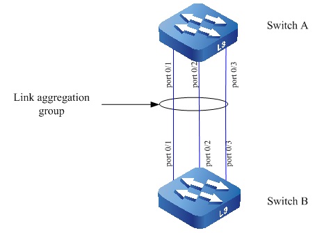
Figure 1: LAG (Link Aggregation) Flow
MLAG
MLAG, called multi-chassis link aggregation, is an extension of LAG. It adds a multi-path capability to traditional LAG. The multi-chassis link aggregation allows a device, like a host or downstream switch to aggregate its ports as one logical port while uplinking them to two different receivers (usually the switches) in a “V” pattern. Also, the two receivers could connect to two another receivers using the multi-chassis link aggregation with all links forwarding, which can be configured as the MLAG domain.
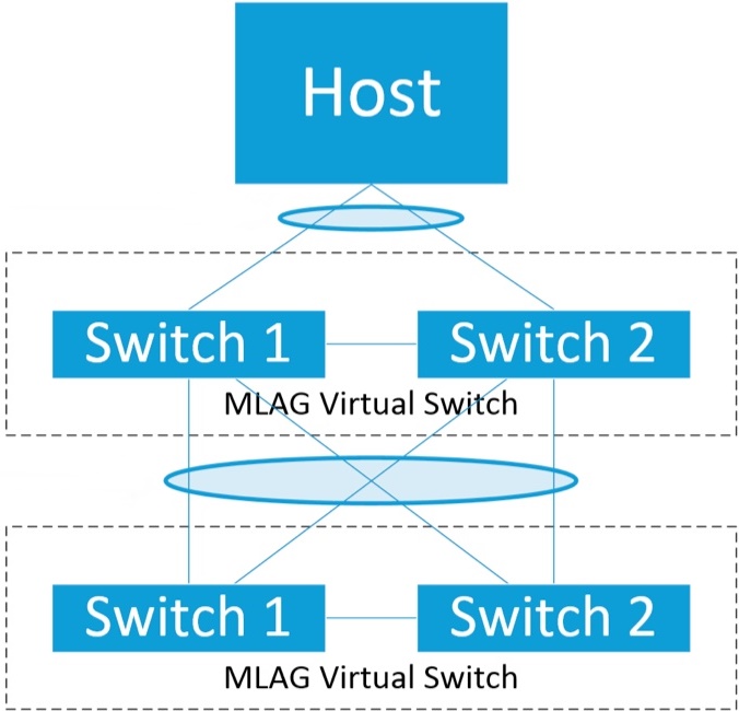
Figure 2: MLAG Flow
Why MLAG Is Needed?
After a basic idea about the multi-chassis link aggregation, we will have a clear vision about the MLAG advantage. That’s the answer why many seasoned technicians recommend this solution.
- The network traffic can be evenly distributed by aggregating multiple Ethernet ports across two switches.
- The bandwidth will be increased after bundling more links into the LAGs.
- The network efficiency gets improved. Especially, if one link fails, the traffic can be forwarded through the other available link and the logical aggregated link remains in the
up state . - Offers stability with dual management and control planes
- Able to upgrade one switch at a time without affecting other devices
- Improves network resiliency and reduces network downtime as well as expenses.
Figure 3: MLAG Application
How to Configure MLAG?
In this part, we will briefly introduce the procedures to configure multi-chassis link aggregation with single-tier on a pair of layer2/3 Ethernet switches, such as the S5800-8TF12S 12-port 10Gb switch. With the support for advanced features, including MPLS, IPv4/IPv6, SFLOW, SNMP, this switch is an ideal choice for the multi-chassis link aggregation of the 10G network.
Procedures:
Step 1: Create the inter-switch connection (ISC) VLAN for carrying the multi-chassis link aggregation control traffic. Just as the following figure shows, you need to make the virtual switches A1 and A2 in 10G uplinks with the two S5800-8TF12S switches separately.
Step 2: Create and configure the multi-chassis link aggregation peer. That means you need to wire the two S5800-8TF12S switches together. At here, the two S5800-8TF12S switches act as a logical entity, which forms the peer link. One switch will be acted as the master and the other will be the slave. After the configuration, they can synchronize info through peer link in a real time.
Step 3: To go further to MLAG + MLAG configuration, the switch A1 or A2 can also be linked to the other two switches. In that way, the 4x10G uplink bandwidth can be achieved.
Step 4: Verification. After finishing all the above steps, you still have to verify that the multi-chassis link aggregation group has been created and is working properly.
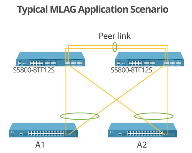
Figure 4: Typical MLAG Application Scenario
Summary
From the above configuration, we can see that the multi-chassis link aggregation is one of the good solutions to improve your network bandwidth and performance. As for the other solution for multiple fiber switches connecting, you can refer to this article: MLAG vs VPC: What’s the Difference?
What Does BASE-"n" Mean for Fiber Optic Transceiver?
The networking is a very complicated field. Especially, when it intertwines with many terms, it’s easy to make beginners get lost in it. In this article, we will explore the Ethernet network naming system as Base-“n” and its applications in fiber optic transceiver.
Network Basics
Before the subject, there are two terms we need to have a clear mind. The first one is “megabit”. Put it in a simple way, the “megabit” refers to the data transfer rates of computer networks or telecommunications systems, also called network speed or Internet connection bandwidth. Usually, the “megabit” is measured by the second, which is used as megabits per second. The common network speeds as “megabit” and their relations with Ethernet speed are displayed below:
·10 megabits ·100 megabits – Fast Ethernet ·1000 megabits – Gigabit Ethernet, GbE, including 1000BASE-X, 1000BASE-T, etc. ·10,000 megabits – 10 Gigabit Ethernet, 10GbE, including 10GBASE-X, 10GBASE-T, etc. ·40,000 megabits – 40 Gigabit Ethernet, 40GbE, or 40GBASE-X. ·100,000 megabits – 100 Gigabit Ethernet, 100GbE, or 100GBASE-X.
The other term is “BASE”, also called baseband. Under Ethernet physical layer standards, for example, 10BASE5, 100BASE-TX and 1000BASE-SX, the “BASE” implies the transmission is an unfiltered line not requiring a digital modulation scheme. In the early days, the 10PASS-TS version of Ethernet was used for a signaling scheme similar to a
An Overview of BASE-“n”
In this part, we will have an overview of BASE-“n”. Here, “n” refers to the variable symbols after BASE. The commonly used symbols with “BASE” are listed below:
1. The first letter tells us which kind of wire we are talking about:
- “T” means twisted-pair cable (e.g. Cat5e and Cat6 are popular for today).
- “K” means a copper backplane.
- “C” means balanced copper cable.
- “F” means optical cable.
- “B” uses two wavelengths over a single optical cable.
- “S” means short-range multimode optical cable (less than 2 km).
- “L” means the long-range single mode or multimode optical cable (less than 10 km).
- “E” means extended-range optical cable (10 km to 40 km).
- “Z” means long-range single mode cable at a higher wavelength (up to 80 km).
2. Next is the coding scheme for data on the wire:
- “X” means 4B/5B block coding for Fast Ethernet or 8B/10B block coding for Gigabit Ethernet.
- “R” means 64B/66B block coding.
3. Finally, we have a number representing the number of parallel “lanes” for data:
- “1” would mean serial (non-parallel) but is omitted instead.
- “4” or “10” are available for copper wire.
- Just about any other number could be used for optical lanes or wavelengths.
BASE-“n” Applied in Fiber Optic Transceiver
After having a basic idea about “BASE”, we will use some examples to explain what the BASE-"n" means for fiber optic transceiver.
1. In the old days, 10BASE-T was preferred instead the coaxial 10BASE2. It was a simple 10 megabits baseband signal over common twisted-pair.
2. Later, the fast Ethernet emerged, people concerned that the previous cable versions (usually Cat3) couldn’t support 100 megabits. Then, some chose to use four copper pairs (100BASE-T4) or fiber optics (100BASE-FX). However, currently, nearly every 100 megabits Ethernet connection is 100BASE-TX, using plain two pairs on plain Cat5 cable.
3. As for the Gigabit Ethernet, it had a similar history. In case that two pairs on unshielded Ethernet cables wiring could not handle 1000 megabits per second, the optical (1000BASE-SX) and balanced shielded wiring (1000BASE-CX) were specified. Although the standard of unshielded two pairs was developed (1000BASE-T), it still couldn’t meet the need. Therefore, in today’s Gigabit applications, the 1000BASE-T uses all four pairs of unshielded twist pair wiring on Ethernet cables. For example, the connection for 1000BASE-T SFP fiber optic transceiver is such a case.
Figure 1: 1000BASE-T SFP Fiber Optic Transceiver
4. After the Gigabit Ethernet, the Ethernet world embraces the 10Gigabit technology. It has mostly shifted to the block coding scheme from Fibre Channel, 64B/66B, which is denoted by the letter “R”. The 10Gigabit technology extends the family of fiber optic cables (10GBASE-SR, LR, ER, etc), and a copper backplane interconnects (10GBASE-KR). In applications of 10Gigabit Ethernet, the 10Gb Ethernet switch is popular.
5. With technology moving on, the higher-speed Ethernet has arrived: 40GBASE-KR4 for backplane use, multimode optical 40GBASE-SR4 and 100GBASE-SR10, and long-range single mode optical 40GBASE-LR4 and 100GBASE-LR10. The mostly seen applications of 40G/100GBASE technologies as fiber optic transceivers are 40G QSFP+ fiber optic transceiver and 100G QSFP28 fiber optic transceiver.
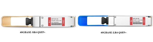
Figure 2: 40GBASE Fiber Optic Transceivers
Summary
In this post, we can see the naming rule of BASE-"n" from 1000BASE to 100GBASE in a more clear way. With this naming system, we can have a better understanding of the naming system for fiber optic transceiver and the development of the Ethernet world.
What Is 10GBASE-T and Why Is It Important?
With the arrival of 10Gbe speed for the Ethernet, all sorts of matching applications spring up one by one. For these applications, the 10GBASE-T technology is one of the most commonly used technologies supporting 10Gbe Ethernet. In this post, we are going to explore this technology. Firstly, we will solve the question: what is 10GBASE-T?
What Is 10GBASE-T Technology?
Actually, the 10GBASE-T refers to a standard (IEEE 802.3) released in 2006. The standard allows chip manufacturers to develop and introduce compliant and interoperable devices, providing connections with the bandwidth of 10 Gbit/s and a maximum transmission distance up to 100 meters over the unshielded or shielded twisted pair cables.
Applications of 10GBASE-T Technology
After answering the question “What is 10GBASE-T”, we will move on the application part. To support the 10GBASE-T technology, there are many applications have come after it. Generally, there are three types of 10GBASE-T-based applications: 10GBASE-T cable, 10GBASE-T transceiver, and 10GBASE-T switch. Among all the three applications, the 10GBASE-T transceiver is commonly discussed by telecommunication technicians. In that case, the application of 10GBASE-T technology in transceiver will be the focus in this part.
What Is 10GBASE-T Transceiver?
Conventionally, the 10GBASE-T transceiver also refers to the 10GBASE-T SFP+ copper transceiver. It is mainly used over Cat6a or Cat7 copper cabling system for 10G transmission with a maximum

Figure 1: What Is 10GBASE-T Transceiver?
Benefits of 10GBASE-T Technology
Knowing “what is 10GBASE-T” as well as the applications under the 10GBASE-T technology especially the 10GBASE-T SFP plus copper transceiver, it’s time to figure out the benefits of it. Generally, there are four points:
- Backward compatibility. The standards-based 10GBASE-T is an interoperable technology, which can be deployed in the existing 1Gbe switch infrastructures in the data centers that are cabled with Cat6, Cat6a or above cabling. In that case, the 10GBASE-T copper network can be used to connect with existing 1G ports or upgraded 10G ports.
- Backward compatibility. The standards-based 10GBASE-T is an interoperable technology, which can be deployed in the existing 1Gbe switch infrastructures in the data centers that are cabled with Cat6, Cat6a or above cabling. In that case, the 10GBASE-T copper network can be used to connect with existing 1G ports or upgraded 10G ports.
- Extended reaching distance. The 10GBASE-T supports the cable length up to 100 meters, enough to support almost all data center topology. In that way, the IT technicians enjoy greater flexibility to cabling all sort of devices in the data center.
- Lower latency. Compared with the latency for 1000BASE-T ranging from sub-microsecond to over 12 microseconds, the 10GBASE-T has a much narrower latency range from just over 2 microseconds to less than 4 microseconds. With a larger packet size, the latency for the 10GBASE-T is more than 3 times lower than the 1000BASE-T.
- Reduced cost. The 10GBASE-T copper network usually uses Cat6 cable for cabling. And Cat6 cables are often cheaper than the comparable length fiber cables. Besides, copper cables like Cat6 do not consume power and their thermal designs require less cooling procedures, extensive savings on operating expenditures within the data center will be saved.
Summary
Conclusively, in this post, three questions have been solved: What is 10GBASE-T technology? What are the applications of the 10GBASE-T? What are the benefits 10GBASE-T? With the development of the 10GBASE-T, it has been a mature and reliable technology. Now, the 10GBASE-T has gradually brightened its way out in the 10Gbe network deployment.