How to Upgrade Cumulus Linux on N-Series Switches?
In previous posts, we have introduced lots of details about Cumulus Linux, a network operating system. Also, we have talked about how to install Cumulus Linux on FS N-series switches like the 100GbE switch. In this post, we will solve another Cumulus Linux related question concerned by most of our users: how to upgrade Cumulus Linux on an N-series network switch?
Before Upgrading Cumulus Linux
Before any update, you should consider the migration and backup of some important data or files in case of
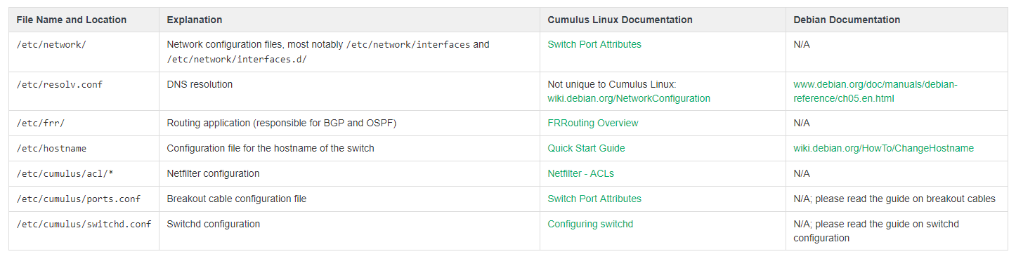
Figure 1: Cumulus Linux Network Configuration Files
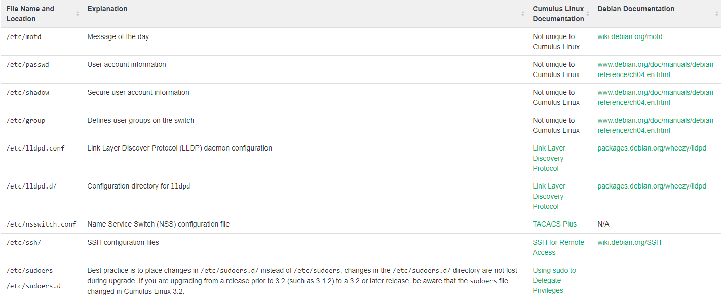
Figure 2: Additional Commonly Used Files
Note: If you are using the root user account, consider including /root/. If you have custom user accounts, consider including /home//.
Upgrading Processes
Basically, there are two methods to upgrade Cumulus Linux: disk image install and package upgrade. According to
Solution 1: Installing A Disk Image
When you are performing a rolling upgrade in a production environment and using up-to-date and comprehensive automation scripts, the disk image installation will be recommended. It enables you to choose the exact release to which you want to upgrade. Moreover, it is the only method available to upgrade your switch like a 10GbE switch to a new release train (for example, from 2.5.6 to 3.7.0) or from a release earlier than 3.6.2. Applying this
1. Back up the configurations
2. Download the Cumulus Linux image you want to install.
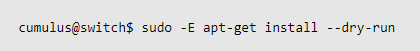
3. Install the disk image with the

Figure 3: Disk Image Install
4. Restore the configuration files to the new release—ideally with automation.
5. Verify correct operation with the old configurations on the new release.
6. Re-install third-party applications and associated configurations.
Solution 2: Upgrading Packages
Package upgrade is recommended if you are upgrading from Cumulus Linux 3.6.2 or later, or if you use third-party applications (package upgrade does not replace or remove third-party applications, unlike disk image install). When upgrading, configuration data stays in place. If the new release updates a configuration file that you changed previously, you are prompted for the version you want to use or if you want to evaluate the differences. Altogether, there are six steps as follows:
1. Back up the configurations from the switch.
2. Apply the following command to fetch the latest update metadata from the repository.

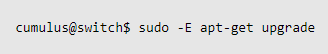
3. Review potential upgrade issues (in some cases, upgrading new packages might also upgrade additional existing packages due to dependencies). Run the following command to see the additional packages that will be installed or upgraded.
4. Upgrade all the packages to the latest distribution.
5. Reboot the switch if the upgrade messages indicate that a system restart is required.
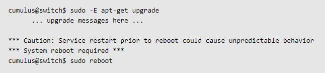
6. Verify correct operation with the old configurations on the new version.
Questions & Answers
Besides the procedures to upgrade Cumulus Linux, we also list some questions concerned most by our FS customers.
1. How to Deal With Upgrade Failures?
Even the most well planned and tested upgrades can result in unforeseen problems. If you fail to upgrade Cumulus Linux, sometimes the best solution is to roll back to the previous state. You can refer to the following three techniques:
- Back out individual packages: If you identify the problematic package, you can downgrade the affected package directly. In rare cases, you might need to restore the configuration files from backup or edit to back out any changes made automatically by the upgrade package.
- Flatten and rebuild: use orchestration tools to re-install the previous OS release from scratch and then rebuild the configuration automatically.
- Backup and restore: restore to a previous state, using a backup captured before the upgrade.
2. Will Future Software Updates for Cumulus Linux Be Free?
For FS N-series switches, the default validity of Cumulus Linux is one year. If Cumulus Linux OS is upgraded after 1 year, the customer can't upgrade it for free and needs to renew the software support. Even if the software support service has been expired, you are allowed to use your current software as usual. By the way, we also provide a three-year software support fee option and a five-year software support fee option. The longer for OS support you choose, the more economical the switch will be.
3. Who Will Cover Technical Support?
FS will provide five-year tech support for the hardware. As for the problems about Cumulus Linux, FS and Cumulus will solve it together. Moreover, as one of the Linux distributions, the source code of Cumulus Linux is also freely available to everyone to use, modify or share such as GitHub. Just like the above question about the software update, the default validity of technical support for Cumulus Linux is one year. One year later, you can renew the support term.
Summary
In this post, we mainly focus on how to upgrade the Cumulus Linux on FS N-series switches. In addition, we list three after-sales related questions frequently asked by our FS customers.
Why 25G Ethernet Switches Are Still Necessary?
It has been about five years since the arrival of 25G Ethernet in 2014. For those years, the 25G Ethernet market has been filled with ups and downs. Facing with the broad adoption for 100G Ethernet and the upcoming new connection speeds of 200G/400G, the use of 25G devices, like the 25G switches, has been in doubt.
A Review of 25G Ethernet
25G Ethernet is one of the standards for Ethernet connectivity in a data center environment, developed by IEEE 802.3 task force P802.3by. Before 25G Ethernet was proposed, the next speed upgrade for data centers was expected to be 40G Ethernet (using four lanes of 10G) with a path to 100G defined as using 10 lanes of 10G. Now, with the 25G Ethernet standard, it supports to have four 25 Gbps lanes to achieve the speed of 100G Ethernet. In that way, it is said that 25G has paved the road for 100G.

Figure 1: 25G Ethernet VS 40G Ethernet
25G Ethernet Switch
With the 25G standard carried out, in 2016, its matching equipment was also available on the market, such as 25G SFP28 transceiver, DAC cable, 25G adapter, and 25GbE switch. Among those devices, the 25G Ethernet switch is the most representative one. Nowadays, the 25G switch market is mainly led by some branded vendors such as 25G Dell, Cisco, Juniper, Arista, and Mellanox switches. Usually, the 25G 48-port switch is the most popular type. Most 25G switches today offer two types of 25GbE interface form factors: QSFP28 that can support 4x25Gbps and SFP28 that can support 1x25Gbps. No matter for TOR (Top of Rack) switch or as the switch to deploy spine-leaf architecture, 25GbE switches will be the good choices.

Figure 2: FS 25G Ethernet Switch N8500-48B6C
Why Still Need 25G Ethernet Switches?
Switch Compatibility
The majority of 25G Ethernet switches in the market support backward compatibility. Because most of their matched optical transceivers are SFP28. And SFP28 is regarded as the enhanced version of SFP+, which is designed for 25G signal transmission. SFP28 utilizes the same form factor as SFP+, but the electrical interface is upgraded to handle 25Gbps per lane. As SFP28 adopts the same form factor as SFP+, SFP28 can connect with SFP+ ports and SFP+ transceiver can also connect with SFP28 ports. SFP28 is compatible with existing data center fiber cabling. Thus, you can greatly reduce the cost of re-architecture data centers and gain great flexibility in creating higher bandwidth during migration. To some extent, it can be both CapEx and OpEx savings.
Port and System Density
The 25G technology is similar to 10G, but the performance is increased by 2.5 times, thus reducing the power and cost per gigabit significantly. 25G Ethernet provides higher port and system density. For example, four 25 Gb/s data streams can be used to produce a 100G path over copper or fiber cable within a compact form factor. This approach also saves on energy consumption and requires fewer top-of-rack (ToR) switches and cables, which cuts much operational expenditure for data center operators in the end.
Price and Performance

Figure 3: Price Comparison by Connection Speed
As we can see in the Crehan forecast in figure 3, 25G delivers on both fronts with better price and performance. While 25G Ethernet is slightly more expensive than the 10G pricing, when valued with price and performance it is much cheaper on a per Gbit/s of bandwidth.
In fact, the 25GbE pricing is very competitive, with only a 30%-40% premium over 10GbE and this premium is expected to come down over time. To achieve these competitive pricing levels requires devices that are optimized to support 25GbE. In that case, deploy 25G devices, such as 25G Ethernet switches are necessary.
Summary
With the trend for higher Ethernet bandwidth, the demand for 10G Ethernet has been in decline. Before the 200G/400G Ethernet becomes mature, 25G shares lots of incomparable strengths to be considered as the proper choice to prepare for the upcoming migrations. In the context of that, 25G devices, such as 25 Ethernet switches are playing indispensable roles.
What Are the Commonalities of Switches Supporting Cumulus Linux
As the first full-featured Linux based operating system (OS), Cumulus Linux has injected great possibilities and new vitality in networking field in these two years. Due to its great effort in open networking, Cumulus Linux has been one of the three leading OSs in the market. The

Figure 1: FS Collaborates with Cumulus Networks
An Overview of Cumulus Linux
Cumulus Linux is a flexible open network operating system, which can be installed on various open switches, including the layer 2 switch and layer 3 switches. The code used to build Linux is free and available for users to view or edit. Therefore, it looks like the world’s largest data center that allows users to automate, customize and scale using web-scale principles. After the installation of the Cumulus Linux OS, the open switch can act as a Linux server.

Figure 2: Cumulus Linux
Similarities of Open Switches Supporting Cumulus Linux
Featured with supporting a broad partner ecosystem, the Cumulus Linux gives customers more options and flexibility in data center networking regarding switch type, CPU, chip type, and supported transceivers.
Switch Type
Generally, open switches that support Cumulus Linux are bare mental switches coming with open network install environment (ONIE). In that case, no matter you have a
CPU
The open switch CPU that supports Cumulus Linux OS usually comes in three types: ARMv7, PowerPC, and x86_64. Among these three types, x86_64 is the most popular one, adopted by most vendors, such as Dell, HPE, Mellanox, and FS.
Chip Type

Figure 3: Chips of Open Switches
Currently, Broadcom chip and Mellanox chip are the major roles of switch chip. The Mellanox type is usually used by Mellanox itself or Penguin. Therefore, the Broadcom type dominates the largest switch chip market share, installed by the most brand vendors or the third party suppliers.
Supported Transceivers
Since most open switches support high-speed transmissions, the matching transceivers are QSFP28, QSFP+, and SFP28. Only some 10G and 1G open switches will need to use SFP+ and SFP transceivers. By the way, viewing the trend, you will find 25G Ethernet has been deployed by many enterprise users in recent years for high bandwidth need. Accordingly, the 25G open switch has been a more economical and efficient choice than 1G or 10G switches. Also, the 25G switch will be the best solution to pave the road for the upcoming 100G/400G Ethernet in the future.
Summary
Just like the agility and simplicity the Cumulus Linux has advocated, it brings a truly economical and open network environment for users. With so many choices for open switch type, CPU, chip, and supported transceivers, it liberates the choices for open switches, which begets an open networking market in the end.
DWDM Networks over Long Distance Transmission
With the ever-increasing need for higher bandwidth, DWDM technology has been one of the most favorable optical transport network (OTN) applications. In this post, we will reveal FS.COM DWDM-based network solutions over various transmitting distances as well as some suggestions for the DWDM networks deployment.
DWDM Networks Basics
As usual, let’s review some basics of DWDM networks. In this part, we will figure out two questions: What is DWDM? What are the components of DWDM networks?
DWDM Technology
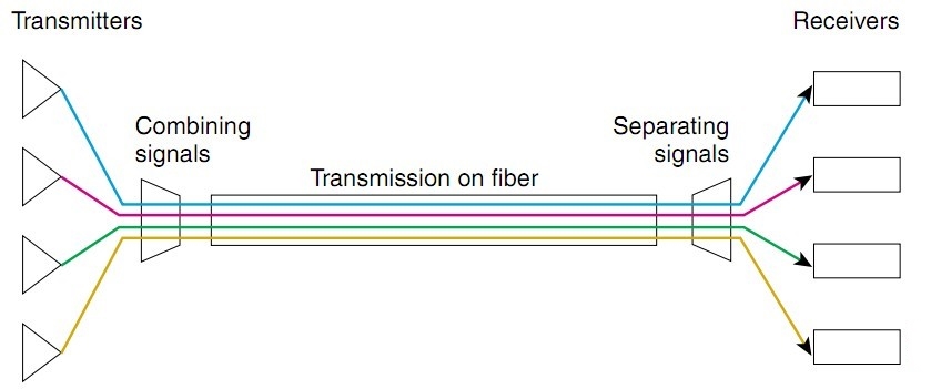
Figure 1: DWDM Networks
DWDM (Dense Wavelength Division Multiplexing) is an associate extension of optical networking. It can put data signals from different sources together on a single optical fiber pair, with each signal simultaneously carried on its own separate light wavelength. With DWDM, up to 160 wavelengths with a spacing of 0.8/0.4 nm (100 GHz/50 GHz
DWDM Networks Components
Conventionally, for DWDM networks, there are four devices showed as below that are commonly used by IT workers:
- Optical transmitters/receivers
- DWDM mux/demux filters
- Optical add/drop multiplexers (OADMs)
- Optical amplifiers transponders (wavelength converters)
DWDM Networks Over Long Distance Transmission Solutions
Scenario 1: 40 km Transmission
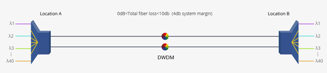
Figure 2: 40km DWDM Network
For this case, the 80km DWDM SFP+ modules and 40ch DWDM Mux/
Scenario 2: 80 km Transmission
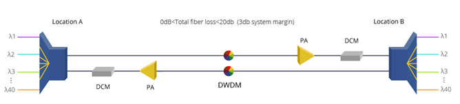
Figure 3: 80km DWDM Network
Deploying this 80 km DWDM network, we will still use 80km DWDM SFP+ modules and 40ch DWDM Mux/
Scenario 3: 100 km Transmission
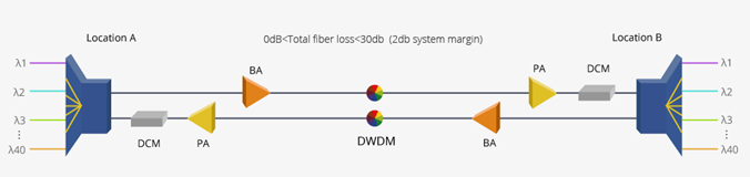
Figure 4: 100km DWDM Network
Under this scenario, the devices used in scenario 2 still need to remain. Since the transmission distance has been increased, the light power will be decreased accordingly. Besides that, you will also need to use booster EDFA (BA) to amplify the optical signal transmission of the 80km DWDM SFP+ modules.
By the way, if you want to extend DWDM transmission distance, you can read this post for solutions: Extend DWDM Network Transmission Distance With Multi-Service Transport Platform.
Factors to Consider in Deploying DWDM Networks
1. Being compatible with existing fiber plant. Some types of older fiber are not suitable for DWDM use. Currently, standard
2. Having an overall migration and provisioning strategy. Because DWDM is capable of supporting massive growth in bandwidth demands over time without forklift upgrades, it represents a long-term investment. Your deployment should allow for flexible additions of nodes, such as OADMs, to meet the changing demands of customers and usages.
3. Network management tools. A comprehensive network management tool will be needed for provisioning, performance, monitoring, fault identification and isolation, and remedial action. Such a tool should be standards-based (SNMP, for example) and be able to interoperate with the existing operating system. For example, the FMT DWDM solutions from FS.COM are able to support kinds of network management, including NMU line-card, monitor online, simple management tool, and SNMP.
4. Interoperability issues. Because DWDM uses specific wavelengths for transmission, the DWDM wavelengths used must be the same on either end of any given connection. Moreover, other interoperability issues also need to be considered, including power levels, inter- and intra-channel isolation, PMD (polarization mode dispersion) tolerances, and fiber types. All these contribute to the challenges of transmission between different systems at Layer 1.
5. Strategy for protection and restoration. There might have hard failures (equipment failures, such as laser or photodetector, and fiber breaks) and soft failures such as signal degradation (for example, unacceptable BER). Therefore, you need to have a protection strategy while deploying a DWDM network.
6. Optical power budget or link loss budget. Since there might be an optical signal loss over the long distance transmission, it’s critical to have a link loss budget in advance.
Summary
Bringing great scalability and flexibility to fiber networks, the DWDM networks solutions obviously enjoys plenty of strengths, which is also proved to be future-proof. In this post, we make a revelation of the DWDM-based network over long distance transmission. Also, some tips for deploying a DWDM network has also been shared for your reference.
Open Switch—One Contributor to Open Source Network
With the higher and higher demand for network agility and scalability, traditional networking has been no longer satisfying. In that case, the open source network has been an urgent need. To meet with this new trend, here comes our open switch, a great contributor to the open networking.
What Is Open Switch?
Open switches refer to switches in which the hardware and software are separate components that can be changed independently of each other. That means you will gain more flexibility to tailor your own network switch. Conventionally, the open source switch in the market can mainly be classified into the bare metal switch, white box switch, and

Figure 1:Open Switch
Open Switch Hardware
The open hardware means the hardware of an open switch can support multiple operating systems (OS). This is in contrast to closed switches, in which the hardware and software are always purchased together. For example, if you buy a Juniper EX or MX you also buy JUNOS; if you buy a Cisco Catalyst switch you buy IOS. However, things will be different with open switches. In the context of that, no matter which type of open source switch you are using, it’s possible to support many operating systems instead of a proprietary one. By the way, the hardware manufacturers of the open switch are primarily Taiwanese, including Accton, Quanta QCT, Alpha Networks, and Delta Computer. These same companies are original design manufacturers (ODMs) for many of the mainstream switch vendors.

Figure 2: Open Hardware
Open Switch Software
The open software signifies that an OS can be run on multiple hardware configurations. As we mentioned before, you don’t need to buy an OS from the original brand of your switch hardware. For example, if you have Cumulus Linux, you can buy a layer 3 switch without a brand label. They still work well with each other. In the past, most people have no choice but to use

Figure 3: Cumulus Linux Software
Why Choose Open Switch?
- With an open source switch, more flexibility, and options can be enjoyed. There is no need to configure your switch as in the past or wait for vendors to release new software or hardware.
- It brings the open source network to operators, enterprises, third-party vendors and network users, accelerates the innovation speed of new services and functions of the network deployment, and takes users closer to SDN (software-defined network) and NFV (network functions virtualization).
- The network simplicity and reliability can be improved through the automated centralized network device management, unified deployment strategies, and fewer configuration errors.
- The network flexibility and scalability have been greatly increased, which will also save much cost and time for IT workers and enterprises.
Summary
In this post, we make an exploration of the open switch. From the introduction to its hardware, software, and benefits, we can understand why the open switch has been a great facilitator for open networking.
An Overview on EVPN and LNV
Bombarded with assorted network applications and protocols, the technologies and solutions for network virtualization delivery have been enriched greatly over past years. Among those technologies, VXLAN, also called virtual extensible local area network, is the key network virtualization. It enables layer 2 segments to be extended over an IP core (the underlay). The initial definition of VXLAN (RFC 7348) only relied on a flood-and-learn approach for MAC address learning. Now, a controller or a technology such as EVPN and LNV in Cumulus Linux can be realized. In this post, we are going to make an exploration
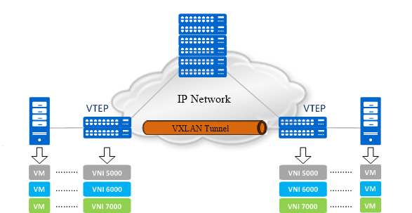
Figure 1: VXLAN
What Is EVPN
EVPN is also named as Ethernet VPN. It is largely considered as a unified control plane solution for the controller-less VXLAN, allowing for building and deploying VXLANs at scale. The EVPN relies on multi-protocol BGP (MP-BGP) to transport both layer 2 MAC and layer 3 IP information at the same time. It enables a separation between the data layer and control plane layer. By having the combined set of MAC and IP information available for forwarding decisions, optimized routing and switching within a network becomes feasible and the need for flooding to do learning gets minimized or even eliminated.
What Is LNV
LNV is
The Relationship Between EVPN and LNV
From the above wiki of the EVPN and LNV, it’s easy for us to notice these two technologies are both the applications of VXLAN. For LNV, it can be used to deploy VXLAN without an external controller or software suite on the bare-metal layer 2/3 switches running Cumulus Linux network operating system (NOS). As for EVPN, it is a standards-based control plane for VXLAN, which can be used in any usual bare-metal devices, such as network switch and router. Typically, you cannot apply LNV and EVPN at the same time.
Apart from that, the deployments for EVPN and LNV are also different. Here, we make a configuring model for each of them for your better visualization.
EVPN Configuration Case
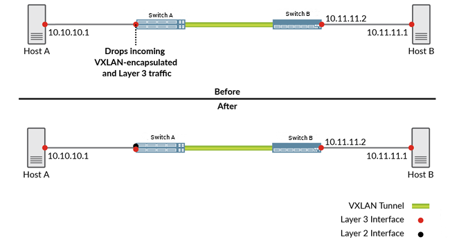
Figure 2: EVPN
In the EVPN-VXLAN network segments shown in Figure 2 (Before), hosts A and B need to exchange traffic. When host A sends a packet to host B or vice versa, the packet must traverse the switch A, a VXLAN tunnel, and the switch B. By default, routing traffic between a VXLAN and a Layer 3 logical interface is disabled. If the functionality is disabled, the pure Layer 3 logical interface on the switch A drops Layer 3 traffic from host A and VXLAN-encapsulated traffic from the switch B. To prevent the pure Layer 3 logical interface on the switch A from dropping this traffic, you can reconfigure the pure Layer 3 logical interface as a Layer 2 logical interface, like Figure 2 (After). After that, you need to associate this interface with a dummy VLAN and a dummy VXLAN network identifier (VNI). Then, an Integrated routing and bridging (IRB) interface need to be created, which provides Layer 3 functionality within the dummy VLAN.
LNV Configuration Case
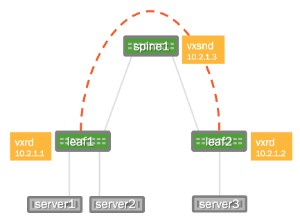
Figure 3: LNV
The
Summary
In this post, we have introduced the two techniques of network virtualization: EVPN and LNV. These two applications of network virtualization delivery share some similarities, but also quite a lot of differences. Being satisfied with the simplicity, agility, and scalability over the network, the
MTP Solutions for High-Density Needs
With the ever-increasing demands for high-density backbone cabling. MTP solutions have enjoyed widespread popularity. In this post, we will have an exploration of two MTP solutions: MTP cable and MTP cassette. For those who are unfamiliar with this term, it’s necessary for us to get started from its basics.
Background Information on MTP
In this part, you are required to acquire three terms: MTP, MPO, and polarity.
MPO
MPO stands for “multi-fiber push on” connector. Usually, it refers to a type of a multiple fiber core connector, defined by IEC-61754-7 (
MTP
MTP is
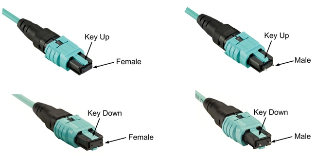
Figure 1: MTP Connectors
Also, there are guide grooves (keys) on the top side of the factory terminated MTP/MPO connectors, which ensure that the adapter holds the connector with the correct ends aligned with each other. According to the key, the MTP/MPO connector come with two types. One is “key-up to key-down”, which means the key is
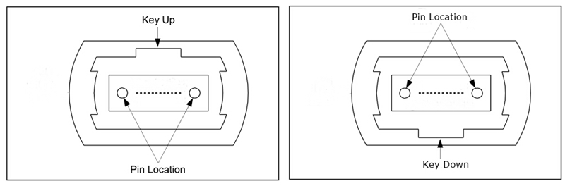
Figure 2: MTP Connector Structure
Polarity
In any installation, it is important to ensure that the optical transmitter at one end is connected to the optical receiver at the other. This matching of the transmitting signal (Tx) to the receiving equipment (Rx) at both ends of the fiber optic link is referred to as polarity.
MTP Solutions
For MTP-based solutions, there are two frequently used applications: MTP cable and MTP cassettes. They are the best choices for providing a simple, cost-effective, and structured cabling system.
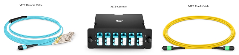
Figure 3: MTP Solutions
MTP Cables
MTP cables usually consist of the MTP connectors and the fiber optic cables. Sometimes, the LC connectors are used, which we will expound in the following part. As for fiber cables, they are typically used in OS2, OM3 or OM4. With different applications, the MTP cable can be classified into MTP trunk cable and MTP harness cable.
MTP Trunk Cable
Serving as a permanent link, the trunk cable is designed to connect MTP modules to each other. It’s available in 12, 24, 48 and 72 fibers. For the ends, the cable is commonly found to be terminated with 12-fiber or 24-fiber MTP connectors. When it comes with the polarity of the patch cord, there are three different types (type A, B, and C), which is defined in the TIA standard. In the following figures, the three different connectivity methods for 12-fiber and 24-fiber MTP trunk cable are showed respectively.
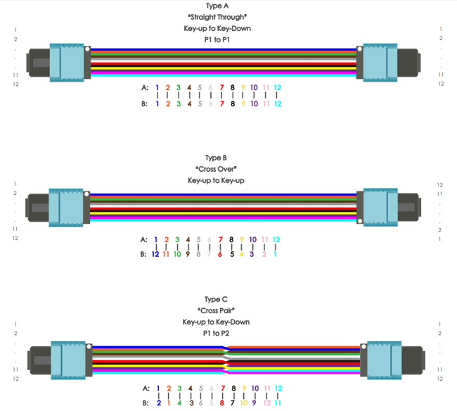
Figure 4: 12-Fiber MTP Trunk Cable
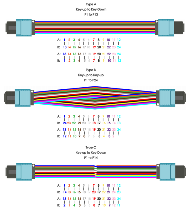
Figure 5: 24-Fiber MTP Trunk Cable
MTP Harness Cable
MTP harness cable is used to provide a transition from
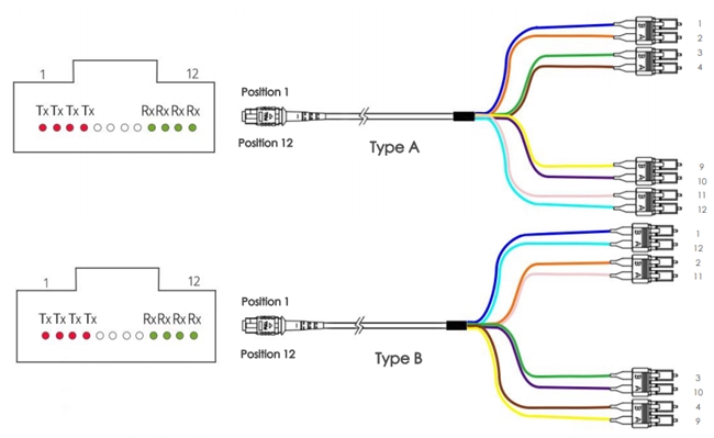
Figure 6: 12-Fiber MTP Harness Cable
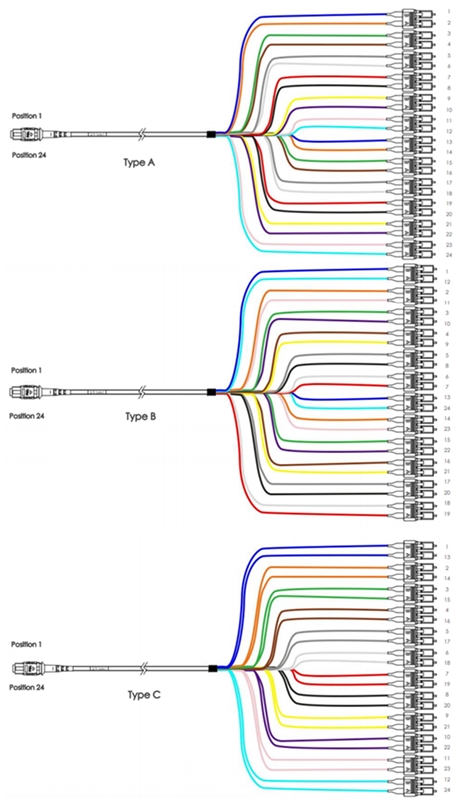
Figure 7: 24-Fiber MTP Harness Cable
MTP Cassette
MTP-cassette is a kind of pre-terminated cassette module. It enables the “transition” from ribbon cables terminated with MTP connectors to the LC or SC interface on the transceiver terminal equipment. Conventionally, the MTP cassette is loaded with 8, 12 or 24 fibers and have LC or SC adapters on the front side and MTP at the rear. Nowadays, the three most widely used cassettes are MTP-8, MTP-12, and MTP-24 cassettes, or also known as Base-8, Base-12, and Base-24 MTP cassettes. For MTP-8 cassette, it is only available in Type A. While MTP-12 and MTP-24 cassettes both come with Type A and Type AF. For their polarity details, please refer to the following figures.
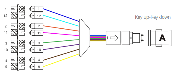
Figure 8: MTP-8 Cassette
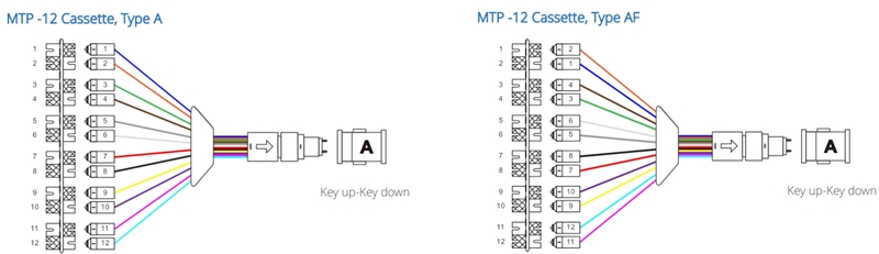
Figure 9: MTP-12 Cassette
Figure 10: MTP-24 Cassette
Summary
In this post, we make an overview of MTP, including what the MPO, MTP, and the polarity are. Then we share three types of MTP-based solutions for high-density networking: MTP trunk cable, MTP harness cable, and MTP cassette.